Atmel AVR
Bing translate into ENG
Microchip PIC
Mixed
Motorola HC05
ST ST6
Zilog Z8
Home
| Last update: 21/06/2023 Atmel AVR |
Other pages in this section: Microchip PIC Mixed Motorola HC05 ST ST6 Zilog Z8 Home |
| Attenzione: Tutto ciò che trovate nel sito è stato realizzato da me ed è disponibile gratuitamente per fini non commerciali. Non mi assumo alcuna responsabilità per le eventuali inesattezze contenute nei programmi e/o negli schemi elettrici e per OGNI POSSIBILE DANNO derivante dall'uso del materiale messo a disposizione. Effettuando un download, IMPLICITAMENTE ACCETTATE di utilizzare quanto prelevato sotto la VOSTRA ESCLUSIVA responsabilità . | Warning: Everything found at the site was made by me and is available free for non-commercial purposes.I do not take any responsibility for any inaccuracies contained in the programs and / or wiring diagrams and EVERY POSSIBLE DAMAGE arising out of the material made available. By doing a download, you IMPLICITLY AGREE to use as taken under YOUR EXCLUSIVE responsibility. |
 |
:: Roboclock. 2 x 12 leds alarm clock with glass ringer -- Roboclock. Sveglia con display 2 x 12 led e suoneria a bicchiere |
    I realized this Alarm Clock for my son that has some problem to wake-up in the morning...
   The circuit was realized with an AT90S2313 micro from Atmel. The reason for this old version is that I built
    it in the 2005, but you can use the new type ATtiny2313 without any problem, 'cause is pin and code compatible.
   Only remember to set the fuses for external oscillator (the crystal 4.096 MHz) and NO watchdog.
   The 'C' source file is supplied in the downloadable ZIP file, so you can modify or rearrange the project for
    your personal needs. When the time reaches the alarm set, the motor is powered with 50% duty cycle and the
    rotation makes the glass ringing due to the rubber balls mounted on its axis.
   Obviously you can use any other system for sound, like buzzers or similar, but the glass is nice !
   The circuit has a small battery charger that works at a very low charging current and is suited for NiCd batteries.
   The battery is needed in case of mains supply fails, 'cause an alarm clock MUST sound even if power is OFF !

    The file ef093.zip contains:
    - root_1_1.pdf , the electric schematic, page 1
    - root_1_2.pdf , the electric schematic, page 2
    - tn_roboclock.jpg , the picture of the roboclock realized by me
    - a093mio.hex , the hex file ready to be programmed into the micro
    - main.c , the 'C' source file for this device
 |
:: Simple Atmel AVR ATtiny2313 programmer with 74HC00 -- Programmatore per micro Atmel AVR ATtiny2313 con un integrato 74HC00 
|
    Simple programmer for Atmel AVR micro ATtiny2313. The only integrated circuit used is the 74HC00 (or 74HC132),
     then no pre-programmed element is needed to operate. The programmer can be connected to RS232 serial port or
     USB to RS232 converter. The control program for Windows is freely available for download; the source files
     (VB6) are also freely available and are easily modifiable and expandable to meet with other types of micros.
     My circuit has been published on "CQ Elettronica" italian magazine in May 2010 issue. Look at the magazine for
     more details on the circuit and software operations.


    The downloadable file Ef152.zip contains:
     - Schema.pdf --> the electric diagram
     - Top.pdf --> the PCB board design in 1:1 scale
     - Foto.jpg --> the picture of the circuit mounted
     - Atprog-install.zip --> the setup for Windows application

    Note: For installation on Win98SE, you may need to download from the Microsoft website the latest Visual Basic
     Runtime 6 (VBRun60sp6.exe).

    The full VB6 source code for this program is now available at this link:
      http://www.planet-source-code.com/vb/scripts/ShowCode.asp?txtCodeId=73103&lngWId=1
    Questions and answers:
      2010, Oct 25

   Question:
      I have built your Simple Attiny2313 Atmel AVR Programmer. When I run it it comes back with a communication Error.
      Check the Clock or Power Supply. I am using a 5 volt DC Power supply. Also I couldn't get a 74HC132 chip,
      and am using a 74LS132 chip, could this be the problem. Also I made up A serial Cable. Could you please let me
      have your DB9 Wiring for this Cable to fit your unit. DB9 to DB9.
      Thanks
        Neil

    Answer:
      Hello Neil.
      First of all, use an HC series IC; if you can't find the 74HC132, please use a 74HC00 but NOT an LS series IC.
      This can't work 'cause the different input impedence makes the delay circuit timings out of specifications.
      As second, make sure that the programmer circuit and the microcontroller under programming are both powered with
       the same supply (5V or 3V). The microcontroller MUST be powered to work !
      Third: be sure that the microcontroller has its own oscillator connected to xt pins if you programmed the
       internal fuses for external clock !
      The serial port connections are standard, you can connect a flat cable male/female connector to your PC.
      Look at the circuit schematic for details.
      Hope this help... bye
        Emilio
 |
:: Caesar's clock. LCD clock with roman digits -- Orologio di Cesare. Orologio LCD con numeri romani 
|
    Il circuito, basato su micro ATtiny2313, realizza un orologio LCD con numeri romani.
    Alla prima accensione mostra una schermata lampeggiante con la scritta "Tempera tempus"
     per ricordare che si deve effettuare la regolazione.
    La regolazione si effettua tramite il pulsantino.
     1) Premere e tenere premuto il pulsante per circa 3 secondi
         -> sullo schermo appaiono le ore -> rilasciare il pulsante.
     2) Premere nuovamente il pulsante e tenerlo premuto
         -> le ore avanzano da "I" a "XXIV" -> rilasciare il pulsante sull'ora giusta.
     3) Attendere circa 3 secondi
         -> sullo schermo appaiono i minuti.
     4) Premere il pulsante e tenerlo premuto
         -> i minuti avanzano da "nulla" a "LIX" -> rilasciare il pulsante sui minuti giusti.
    Non essendoci una batteria, l'orologio NON mantiene l'ora se va via la corrente.
    Ogni volta che si stacca l'alimentazione, alla riaccensione verrà visualizzato il messaggio
     che ricorda di effettuare la regolazione.

    Nel file Ef162.zip sono contenuti:
     - schematic.pdf lo schema elettrico del circuito
     - roman.hex il file HEX per la programmazione del micro
     - fuses.txt il file di testo con la configurazione dei fusibili per questa applicazione
|
:: DTMF-remote. Use "wireless" sound interface to activate relays with your smartphone or PocketPC -- Attivazione senza fili per relè con Smartphone o PocketPC mediante toni DTMF |
 |
Application circuit controls 2 motors with 3 relaysABC | motor status (0=relay off,as shown in figure; 1=relay ON) --- | --------- 000 | M1 & M2 stop 001 | M1 stop, M2 run clockwise 010 | M1 run clockwise, M2 stop 011 | M1 & M2 run clockwise 100 | M1 & M2 run counterclockwise 101 | M1 run counterclockwise, M2 stop 110 | M1 stop, M2 run counterclockwise 111 | M1 & M2 stop |
 |
:: Electronic lock with RFID key and generic 125KHz RFID reader -- Serratura elettronica con chiave RFID e lettore generico RFID 125KHz |
    The circuit, based on micro ATtiny2313, reads RFID tags at 125 KHz.
    The code of the first tag read after micro burning is stored in the internal earom and then causes
    a pulse of about one second on relay contacts every time that tag is placed near the reader.
    This makes it possible to realize a simple and touchless electronic lock.
    The stored tag, and every other tag that's placed near to the reader, also cause the serial output
    of the inside code, in ASCII format, allowing to implement a generic reader for access control.
    This circuit was published by me on the magazine CQ Elettronica in the May 2009 issue and entitled:
    "RFID reader 125KHz"; consult the magazine for more details on the circuit and implementation.
    To program the micro, the freeware SP12 has been used, in the versions for WinXP or Win2K.
    The batch files included in downloadable ZIP require the use of this software for programming the micro
    (you can easily find it with a Google search). If you have another tool for micro burning,
    the configuration for fuses in the application described is the following:
    // CONFIGURATION Fuses: Ext = 0xFF High = 0xC9 Low = 0xDF
    // Note: SP12 High Fuses used in only 6.1 bits, so 0xC9 (11001001) becomes 0x24 (100 100)

    The file EF150.zip contains:
        main.c - C source program
        schematic.pdf - electric schematic in PDF format
        top.pdf - Printed circuit board layout (single sided) in PDF 1:1 scale
        topprint.pdf - layout of components on the circuit
        rfid.a90 - compiled HEX file ready to be burned into the micro
        wrFuses.bat - batch file to program the micro fuses
        wrProg.bat - batch file to start the firmware programming
        wrEarom.bat - batch file to overwrite the earom (stored tag)
        ef150pic.jpg - photos of the circuit mounted
        interfaces.gif - a couple of circuits to interface the card to a PC or a micro
        earom.txt - text file containing the 5 bytes to erase key tag in earom

    Added Sep 10 2010
    The active range is about 3 cm with the coil shown in figure.
    Better results can be obtained modifying the coil diameter (and the number of turns, obviously).
    Added Ago 30 2009
    Coil has 105 turns of 0.2mm wire wound on 30mm diameter support;
     in the prototype I used the neck of a plastic bottle, visible in the figure.
    Added Feb 28 2010
    Note: The driver SN75176 is used ONLY as power driver, but the circuit works even if you remove
     the chip and simply put a jumper between pins 4 and 6 of the 8 pin socket.
    Obviously, the driver makes more "relaxed" the microcontroller's output pin PB2.
    Note: I received many requests for 'C' or Assembler sources for this program;
    okay, I decided to make it available !
    Added Mar 1 2010
    Note: You can browse the SP12 AVR programmer project at this site/url:
    http://www.xs4all.nl/~sbolt/e-spider_prog.html.
    I have done a personal version of RS232 (or USB-RS232 converter) programmer for ATtiny2313 micro
     using only 74HC00 as active part; it will be added to this site immediatly after been published
     on italian electronics magazine (may be in Maj 2010 issue).
    The fuse map, using my own programmer, is this:
    Added Mar 2 2010
    Oops, someone noticed that the circuit's picture shows an ATTiny2313V-10PU cpu;
     well, the right chip is the one that's in the circuit's schematic diagram: the ATTiny2313-20PU.
    The last one, in fact, can run with the 16 MHz crystal needed by the application, while the first one
     is guaranteed only up to 10 MHz. The reason for the 10 MHz version mounted on board is (simply) that
     I didn't own the fast version and tried (successfully) with the slow one.
    Ok, DON'T LOOK at the picture, look at the schematic diagram !!!
    Added Apr 14 2010
    The C source for this project is available as text file (.C) in the new zipped download;
     the compiler used for this project is the IAR Embedded Workbench KickStart Edition, freely available
     from this link: http://supp.iar.com/Download/SW/?item=EWAVR-KS4 (registration required).

    If you like to use my own Atmel AVR programmer for ATtiny2313 burning, this is the map for fuses:

 |
:: General purpose infrared remote control receiver with RS232 output -- Ricevitore per telecomando a infrarossi per uso generale con uscita RS232 |
    This circuit can receive signals transmitted by an infrared remote control using the NEC protocol,
     or similar, with 32 bits of data.
    The received signal is converted to ASCII and transmitted on the RS232 port with format 19200,N,8,1.
    Power is taken directly from the PC serial port, if you activate the DTR or/and RTS lines.
    To test the circuit you can use the standard Windows HyperTerminal program.
    The circuit transmits three types of information:
     1) the character '@' at micro reset and then every 5 seconds of inactivity (no signal received by
         the infrared sensor)
     2) a string of 8 hexadecimal ASCII characters preceded by '<' (start) and followed by '>' (stop)
     3) the character '#' if you continue to hold down a button on the remote control, with a period
         given by the repetition rate of the remote control (100/200 ms approx.)

    A typical string might be as follows: @@@@<00FF00FF>## where the first 4 characters '@' means that
     there was no activity on the infrared sensor for about 20 seconds, <00FF00FF> is the key code
     received from remote and ## indicates that the key was pressed for 200/400 milliseconds.
    To program the micro was used the freeware version of SP12 for WinXP or Win2K.
    The batch files to program the micro and the fuses that are included in zip file, are tailored for
     this software (you can find it easily with a google search).
    If you have other tools for micro programming, the fuses configuration for the application described is:
     Ext = 0xFF High = 0xCB Low = 0xEC

    The file EF148.zip contains:
        main.c - the 'C' source file
        schematic.pdf - the electric schematic in PDF format
        top.pdf - the PCB layout in 1:1 scale
        topprint.pdf - the components mounting map
        irrx.a90 - the HEX file to burn the micro
        wrFuses.bat - the batch file for micro's fuses programming
        wrProg.bat - the batch file for micro's memory programming
        148pic.jpg - the picture of the working circuit

    Added Mar 3 2010
    Note: I received many requests for 'C' or Assembler sources for this program;
     okay, I decided to make it available !
    Added Mar 15 2010
    This C source has been compiled with the IAR Embedded Workbench KickStart Edition, freely available
     from this link: http://supp.iar.com/Download/SW/?item=EWAVR-KS4 (registration required).
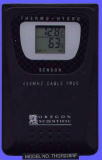  |
:: PC Rs232 interface for Hygro-Thermo 433 MHz remote sensor -- Interfaccia PC Rs232 per sensore Hygro-Thermo a 433 MHz |
  |
:: Clock with oscilloscope output -- Orologio con uscita su oscilloscopio |
 |
:: POV Spinning text: one row led output shows text while spinning -- Scritte rotanti: una striscia di led mostra una scritta quando viene fatta ruotare |
 |
:: Test circuit for LCD display based on NEC µPD7225G controller -- Circuito di test per display LCD basato su controller NEC µPD7225G |
 |
:: Remote control for TV (SALORA): turns ON the TV at programmed time (triggered by alarm clock without buzzer) -- Telecomando per TV (SALORA): accende il televisore all'ora programmata (attivato da sveglietta priva di buzzer) |